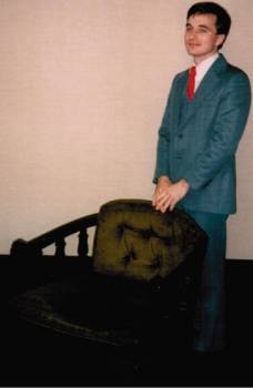
The following pictures show the laboratory that I built with the money I received from the sale of my car (e.g.: a Hornet Hatchback) along with money I received from digging ditches.
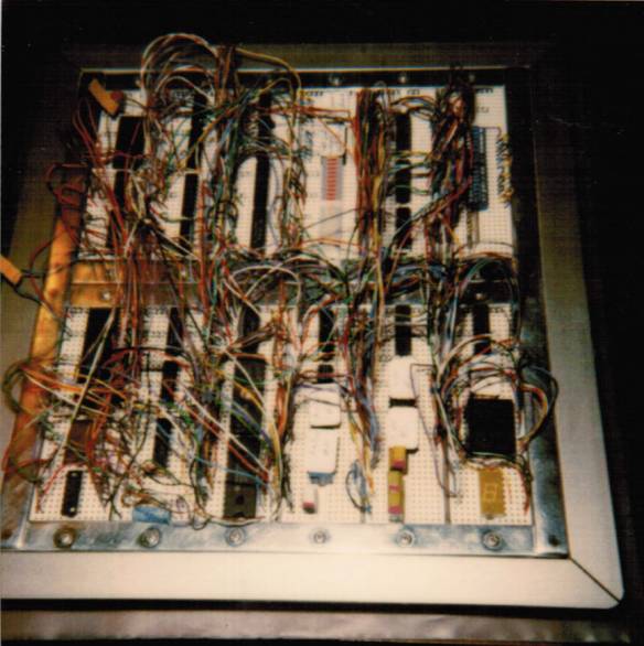
One of the device I built here was the Proto-Scanner, which was a device that would scan circuitry as constructed the Proto-Scanner’s large detachable breadboard (e.g.: 980 connections). The collected PCB data about that circuit’s Node-To-Node connections/list, IC (e.g.: Integrated Circuits) pin-counts and the orientation of the ICs was communicated (via OmniTerm) to my PC for use by a CAD package called SmartWorks, which CAD package performed auto-routing the runs for the new mass producible PCB as represented by the CAD drawings as produced by SmartWorks.
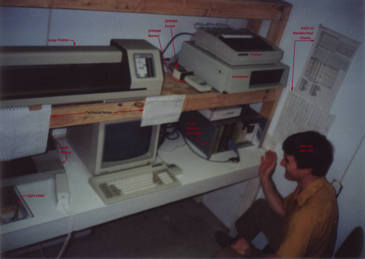
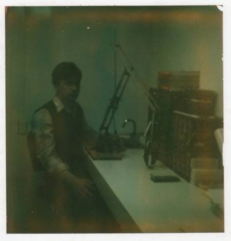
Depicted below is the Proto-Scanner’s card rack as connected to my PC as I was developing the Proto-Drafter system. Typically, I would compile the Z80 assembly code that I wrote and then download it into the Proto-Scanner. However, in order to do that, I had to first write the BIOS (e.g.: Basic Input/Output System) for the Proto-Scanner system, which I burned into the EPROM(s). The EPROM that containing my BIOS, I plugged into my main controller PCB of the Proto-Scanner system and thus this allowed me to perform the aforementioned intercommunication between my PC and my Proto-Scanner system. All firmware, software and hardware tasks I performed myself.
The coupling of the Proto-Scanner, SmartWorks CAD package and the plotter(s) made the complete Proto-Drafter system. In this way, the fundamental parts of a machine that could reproduce its own circuitry was born. Although I did design the system to rapidly convert the PCB information about a circuit that was constructed in the large breadboard of the Proto-Scanner system to be used by the CAD software on the PC to rapidly reproduce circuitry for mass producible PCBs, I stopped short of making the Proto-Drafter system able to reproduce itself, (e.g.: similar to what is going with regard to the current 3-D printers being developed today, which devices have an ability to reproduce themselves physically). Having said that, it is conceivable that if my Proto-Scanner system was married with a 3-D printing system, that a machine that reproduce itself could be engineered (e.g.: being able to reproduce all of its own circuitry and all of its own physical structure), although this would require the system to either be self-aware OR its own structural information would have to be self contained similar to how the DNA is used in organic systems today.
At any rate, also shown below are EPROM burner, EPROM eraser, light table, computer, printer and ASCII conversion charts as well as the plotters that were used to physically draw up the PCB (e.g.: Printed Circuit Boards) for the Proto-Drafter system,
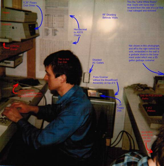
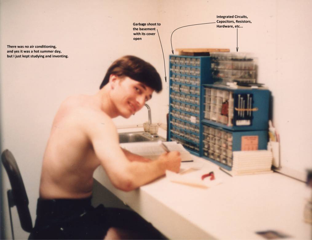
Although not shown, my laboratory was also equipped with AC and DC power, a garbage shoot to the basement (which went into a 55-gallon container) and also a sink to perform the PCB manufacture in-house along with a supply of ICs, capacitors, resistors, etc… Shown below is another view me working in my white laboratory along with a circuit in the Proto-Scanner’s breadboard.
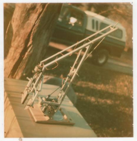
Shown below is my brother Paul who mad a Robotic Arm out of available materials (e.g.: a railroad tie’s plate, and shelving material). Although not shown, I built the Robotic’s Arm control circuit, which sampled the data coming from two joy sticks, with each joy stick providing 4 bits of a each byte sampled at ¼ second intervals. The testing that we did for the Robotic Arm was somewhat simple: (1) Operate the Robotic Arm via the two joy sticks, (2) As the operator was operating the Robotic Arm, save into the RAM the captured data as supplied by the two joy sticks, (3) Put the Robotic Arm back to its original starting position and (4) Replay the operator’s joy stick instructions from the data that was recorded in the RAM and send this data to the motors. When we tested the whole Robotic Arm setup this way, it was remarkable how to see just how well the replay of the captured data caused the Robotic Arm to re-perform the operator’s original movements.
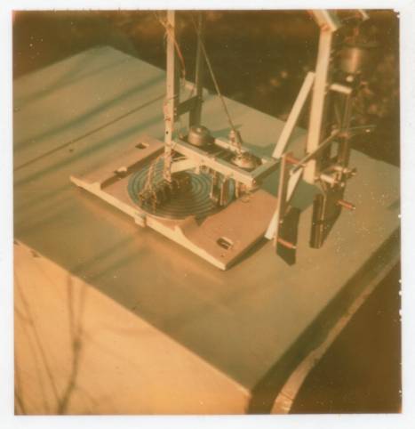
The way my brother Paul constructed the base of his Robotic Arm was to use make a PCB that had concentric circles of runs on it. In this way his Robotic Arm could turn many revolutions without causing cable tangling issues. Additionally the brushes he used to make contact with the concentric circles where made up of copper tubes with spring loaded bearings in each to ensure good electrical contact with each concentric run on the PCB. Also the elbow and shoulder of his Robotic Arm use a lead screw and nuts to perform the lifting/movement of the different parts, including the hand movement.
Shown below, I would work on many hot summer days in my laboratory and there was no air conditioning; Undeterred, I just continued to study and kept on inventing new gadgets.
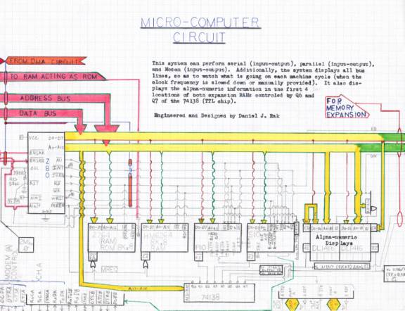
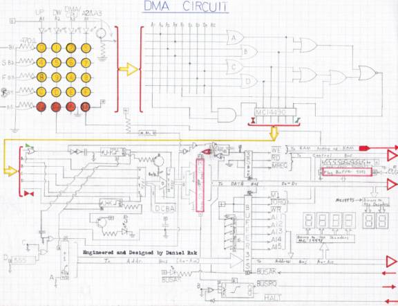
A couple of my early firmware/circuit designs are shown below:
As a young boy, I had a very active imagination, which as I got older, the constant hunger
for knowledge and understanding never stopped. In High School, I would search out and
read such books as the Nutrino by Issac Asimov and about particle accelerators. Life is
still extremely exciting and constantly pregnant with possibilities. As I continue to grow
even after decades of inventing, designing, discovering and exploring, and as I contemplate
how to build my plasma-magetic drive (e.g.: electric jet propulsion) and my 2.4Thz optical
computer, I can see that if I lived forever, it would be impossible for me to ever get bored.